The LHPOST6 is the largest shake table facility in the U.S. and the second largest in the world. It enables ground-breaking experimental research related to structural, geo-structural, soil-foundation-structural, and non-structural components and systems including how these systems behave during realistic multi-component earthquake excitations, and how they should be conceived and designed to resist such excitations best.
LHPOST6 System & Components
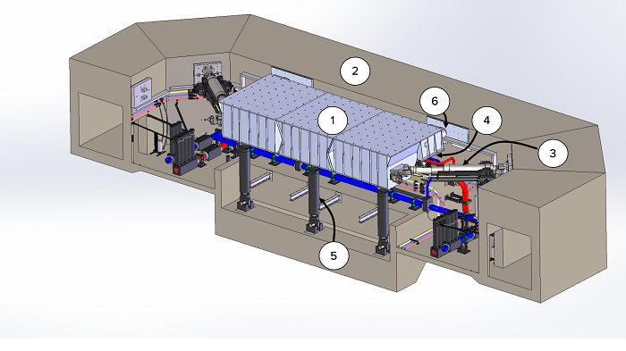
- Component 1 is the 12.2 m long by 7.6 m wide by 2.2 m deep honeycomb steel platen.
- Component 2 is the reinforced concrete reaction mass and the service tunnel that connects to the Hydraulic Power System Building.
- Component 3 consists of the set of four servo-controlled dynamic horizontal actuators mounted in a V-shape configuration.
- Component 4 comprises the six vertical actuators, which support the shake table platen and provide the vertical, roll, and pitch motion capability.
- Component 5 is a set of three nitrogen-filled hold-down struts that passively pre-compress the platen against the sliding bearings (on top of the piston of the vertical actuators) and, consequently, provide the overturning moment resistance.
- Component 6 is a crash protection system as a third line of defense (after the software limit detectors and the physical limit switches) in the case of an uncontrolled table motion condition.
- Component 7 (not shown) is a weatherproofing system consisting of removable concrete planks, removable composite concrete-steel planks, and steel cover plates for protection of the servo-hydro-mechanical equipment installed inside the reaction mass against falling debris.
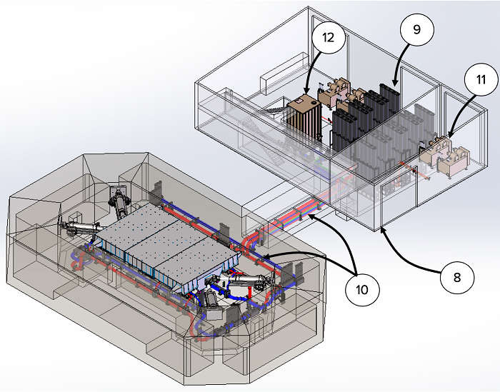
- Component 8 is the hydraulic power system building and service tunnel.
- Component 9 is the accumulator bank in which the oil (hydraulic fluid) is pressurized by the hydraulic power units (pumps) and then discharged at system pressure into the hydraulic pressure lines supplying all the system actuators.
- Component 10 consists of the hydraulic pressure lines (red colored piping) that transport the high-pressure oil from the accumulator bank to the servovalves of all the horizontal and vertical actuators in the shake table pit area. The low-pressure return flow from all the horizontal and vertical actuators is directed to the surge tank through the hydraulic return lines (blue colored piping).
- Component 11 consists of three pumps to pressurize (charge) the accumulator bank before and during a shake table test and one pump to provide the pilot flow to the servovalves of all actuators.
- Component 12 is a surge tank that collects return oil flow.
Basis of Design
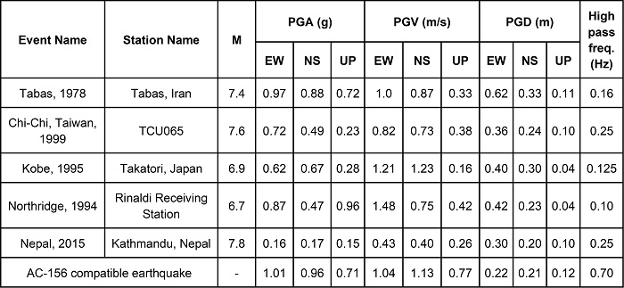
The design of the LHPOST6 was developed in a collaborative effort between UC San Diego and MTS Systems Corporation. The target performance of the LHPOST6 was defined through its ability to reproduce the six tri-axial strong ground motions defined in Table 1 below. These ground motions are from the 1978 Tabas (Iran), 1994 Northridge (California), 1995 Kobe (Japan), 1999 Chi-Chi (Taiwan), and 2015 Nepal earthquakes, and an AC- 156 compatible artificial earthquake record developed for seismic qualification testing.
Table 1: Tri-axial strong ground motion records considered for the preliminary design of LHPOST6.
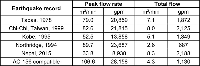
To achieve the desired design criterion, the hydraulic power system was designed using inverse simulation, which takes a target tri-axial ground motion record as input and computes the system demands in terms of displacement, velocity, acceleration, force, servovalve opening, oil flow and pressure. The peak demand flow rate and total demand flow required to reproduce the six considered tri-axial earthquake records are shown in Table 2 below. It is observed that the Chi-Chi and Nepal earthquake records require a total flow demand exceeding 8.0 m3 (2,100 gallons), dictating the need for a 36.9 m3 (9,750 gallon) accumulator bank (75 bottles of 0.38 m3 (130 gallon) each) which can provide approximately 9.0 m3 (2,300 gallons) of oil at 20.7 MPa (3,000 psi).
Table 2: Peak demand flow rate and total demand flow required to reproduce the tri-axial strong ground motion records defined in Table 1; bare table condition.
Acceptance Test Results
For the three components of the 1995 Kobe earthquake record that was used in the Basis of Design, Figure 1 shows the target vs. achieved translational acceleration time histories, Figure 2 shows the target vs. achieved translational velocity time histories, and Figure 3 shows the target and achieved translational displacement time histories. A comparison between target and achieved five-percent damped tri-partite (displacement/pseudo-velocity/pseudo-acceleration) linear elastic response spectra is provided in Figure 4.
The fidelity of the responses are strong, and similar levels of signal tracking fidelity were observed for the other tri-axial earthquake records considered in the LHPOST6 design. The level of fidelity in signal reproduction for the vertical component and other motion components will be further improved through experience gained as we implement advanced control capabilities that are built into the MTS 469D shake table controller such as Adaptive Inverse Control (AIC), On- Line Iteration (OLI) and Specimen Dynamics Compensation (SDC).
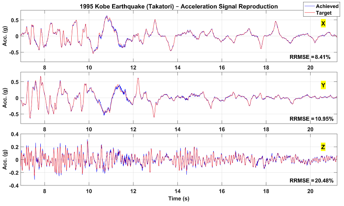
Figure 1: Comparison of target and achieved tri-axial acceleration time histories for the 1995 Kobe earthquake record (see Table 1 in Basis of Design).
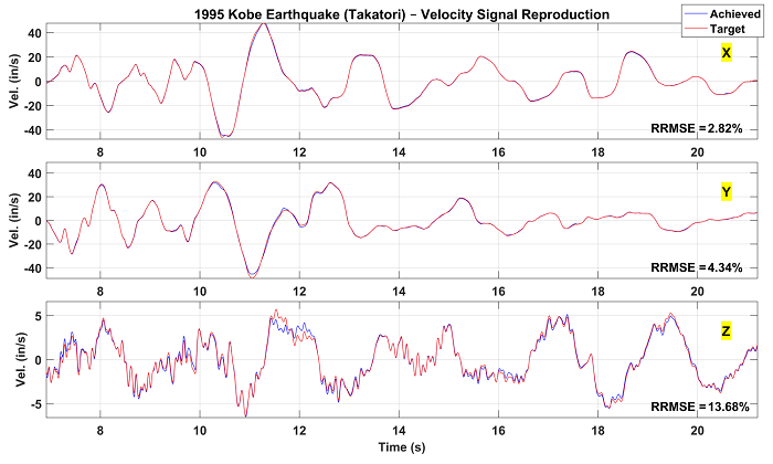
Figure 2: Comparison of target and achieved tri-axial velocity time histories for the 1995 Kobe earthquake record (see Table 1 in Basis of Design).
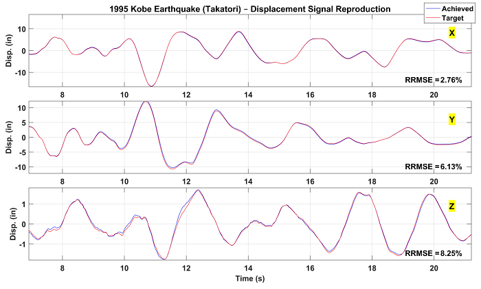
Figure 3: Comparison of target and achieved tri-axial displacement time histories for the 1995 Kobe earthquake record (see Table 1 in Basis of Design).
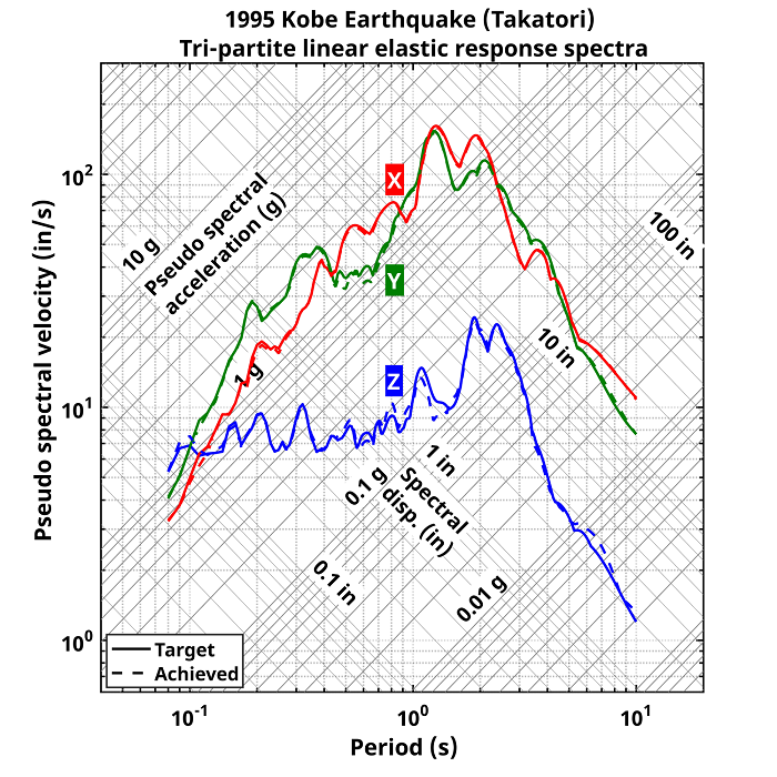
Figure 4: Comparison of the target and achieved 5% damped tri-partite linear elastic response spectra for the 1995 Kobe earthquake record (see Table 1 in Basis of Design).